
Cork. The old standby for creating a roadbed to lay the track on. I used it because it worked best with laying the roadbed directly on the foam. Now that the track center lines have been laid out on the foam, it is time to lay the cork roadbed. This process, for the most part, is fairly easy. The hardest part is splicing the cork to fit where the turnouts will be.
I used the generic beveled cork roadbed that has been a standard for track laying for years. It has a number of benefits, including being easy to cut, beveled, flexible, and cheap. It also is porous, making it adhere well to the foam with foam safe adhesive caulk.
My first step was to seperates the two halves along the beveled cut. The type that I used needed to be cleaned up a little on the edges where the two halves where jointed. To do this, I used a curved edge blade in my hobby knife and ran it along the ragged edge until it was fairly smooth. It doesn’t have to be perfect as I plan on covering the cork with ballast in the future. I just wanted to get it to the general shape.
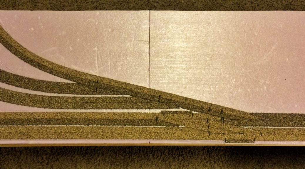
I started first with the two parallel sections of track at the front of the module, and went from there. When I got to the location of the turnouts, I contriued the outside half through the turnout. I then ran the inside half through the diverging leg. This gave me a general form in which to splice the inner pieces into. As I went along, I glued the pieces down onto the foam, then used pins to keep the cork in place while the adhesive cured.
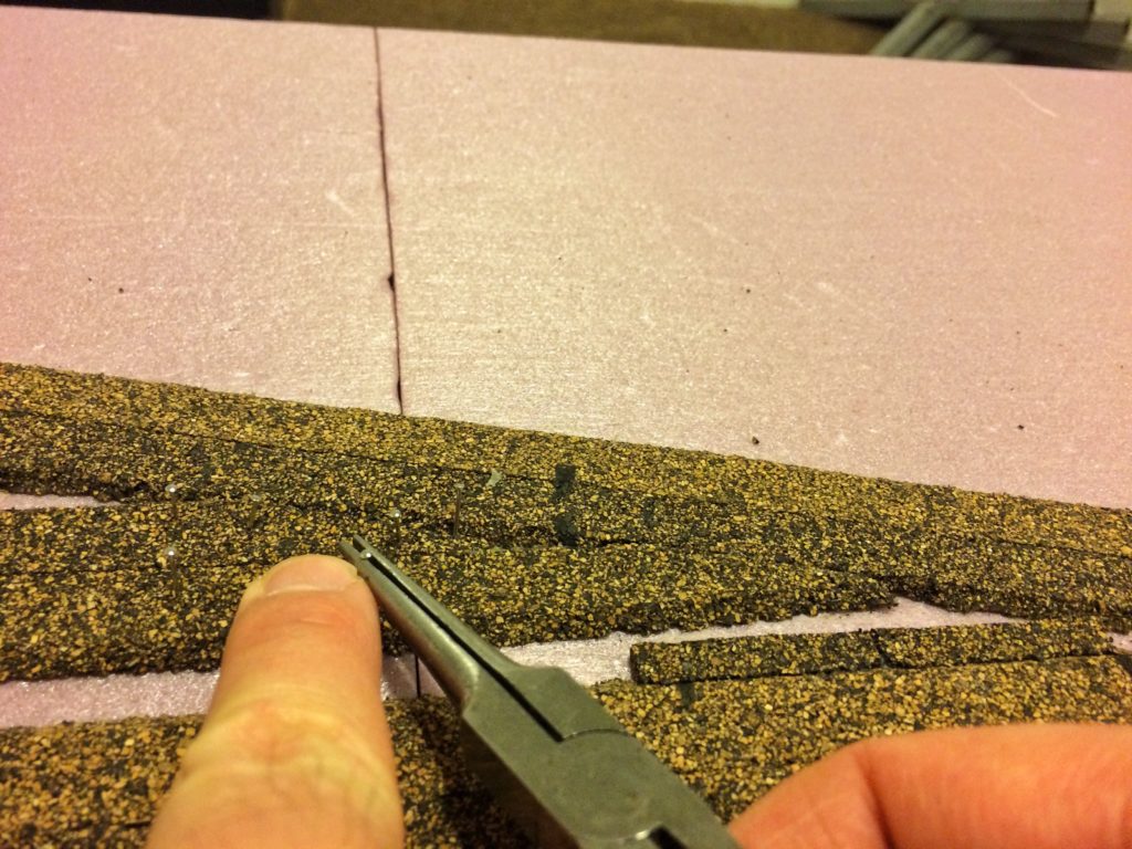
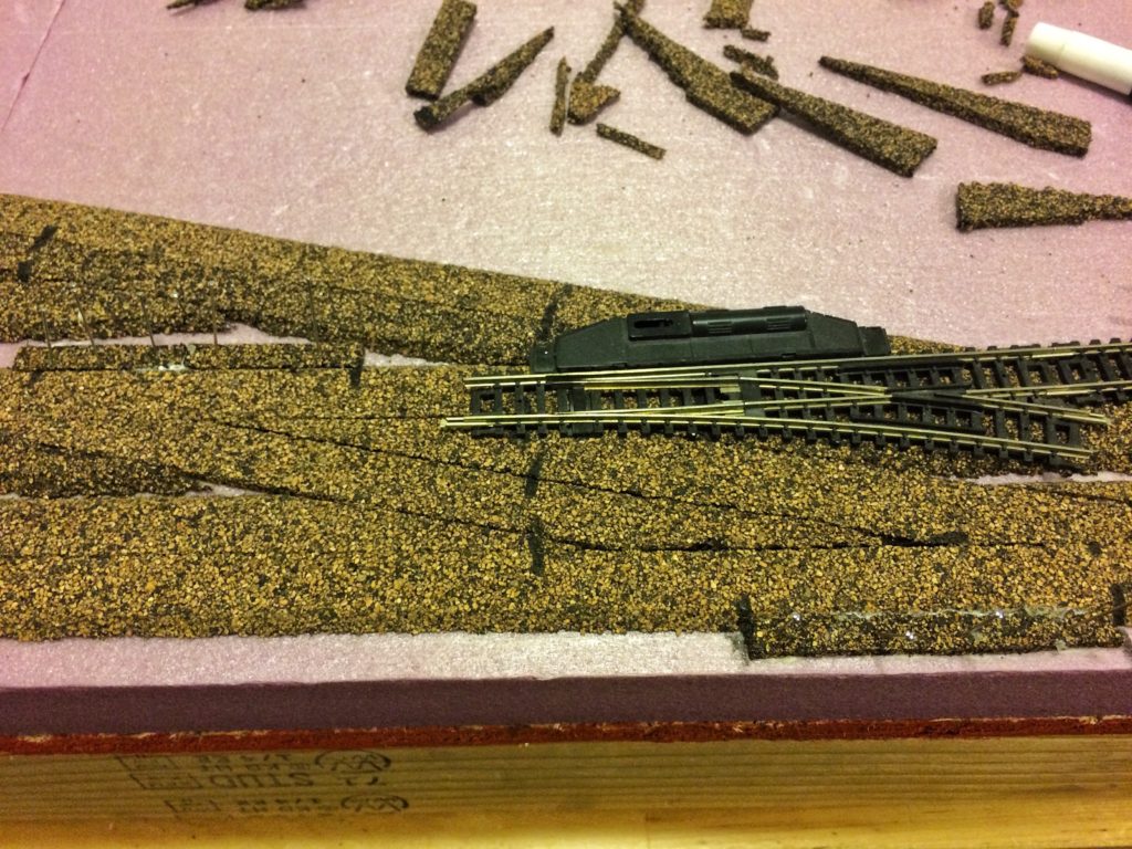
To help guide my spices at turnouts, laid the piece that I am going to cut over the other piece that I already laid down. I then used the edge of the other piece as a guide, and then made the cut by making multiple passes with the knife. The cut piece will then fit almost exactly. I then used a piece of scrap under where the Atlas switch’s toggle to help complete the cork.
For the crossing between the two parallel tracks, I used odds and ends as the distance between the two tracks wasn’t that great. I didn’t want to deal with the beveled edges so I put the beveled edges in the middle so the out side edges where square. Once the ballast is in place, the hard edge won’t be noticeable.
I continued following the center lines that I marked on the foam for the rest of the module, cutting and splicing as needed. After about an hour I had the cork laid and was ready to start laying track.