Wiring and soldering wires is a fairly straightforward process. Once you have done it a couple of times, it becomes fairly easy, although repetitive, process. I recommend practicing on some scrap track before tackling the layout itself if you haven’t done this before.
Soldering Feeder Wires
I wanted to attache feeders to each section of track so there wouldn’t be any dead spots. Since one of the purposes of the module is experimentation, I decided to do some on how I attached the feeder wires to the track. I found a couple of various methods and tried them out. This way I know which method I would like to use on my layout. My primary goal is to have the feeder wire as invisible as possible.
One thing you need to do is to make sure you use a supper fine or chisel tip on your soldering iron. There is very little metal on model railroad track to soak up the heat, especially in N scale! If you are not very careful, you’ll melt the ties!
After some practice, I discovered a few tricks:
- Flux is a must! It helps the solder flow better between the joints.
- Use small diameter solder, because we are dealing with small rails, and you won’t need a lot. It will also melt quicker hopefully saving some ties in the process. The solder that I used for this project is .80mm (.031″) in diameter.
- Tin both the wire and rail before soldering. This will cut down on the amount of heat that is needed to join both pieces together.
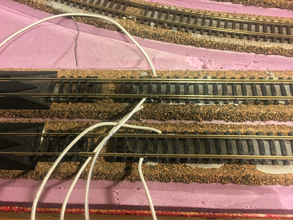
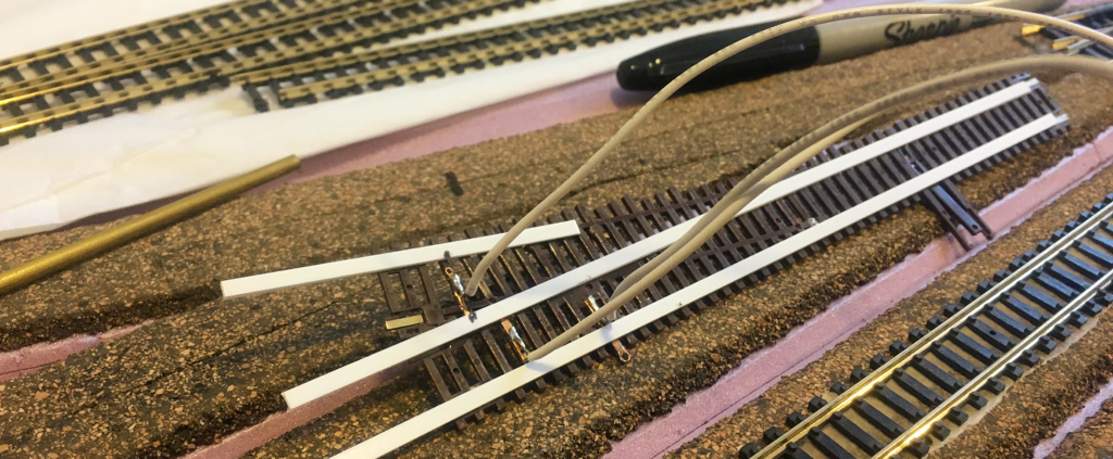
I tried the solder to the outside of the rail method. While this is fairly easy, it leaves a fairly large for N scale size blob of solder on the outside of the rail. My opinion is that while this is fine in larger scales, I think with N scale’s smaller rail, the results too noticeable. It is hard to get the wire to site in the web of the rail, if the N scale rail you are using has any webbing at all. I will have to see if this becomes less noticeable when the rail is painted.
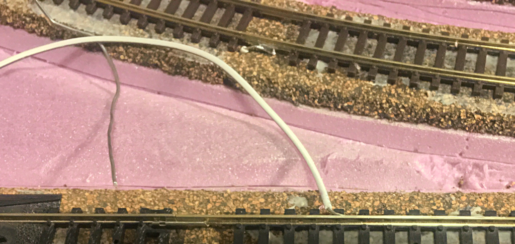
Another method was to remove a couple of ties and then solder the wire to the bottom fo the rail (see just above the white wire in the photo above). While this made the connection a lot less noticeable, after the track is installed, you are left with a sizable gap between rails. I think it will make it harder to put ties in those locations because of the reduced clearance between the soldered wire and rail and the road bed.
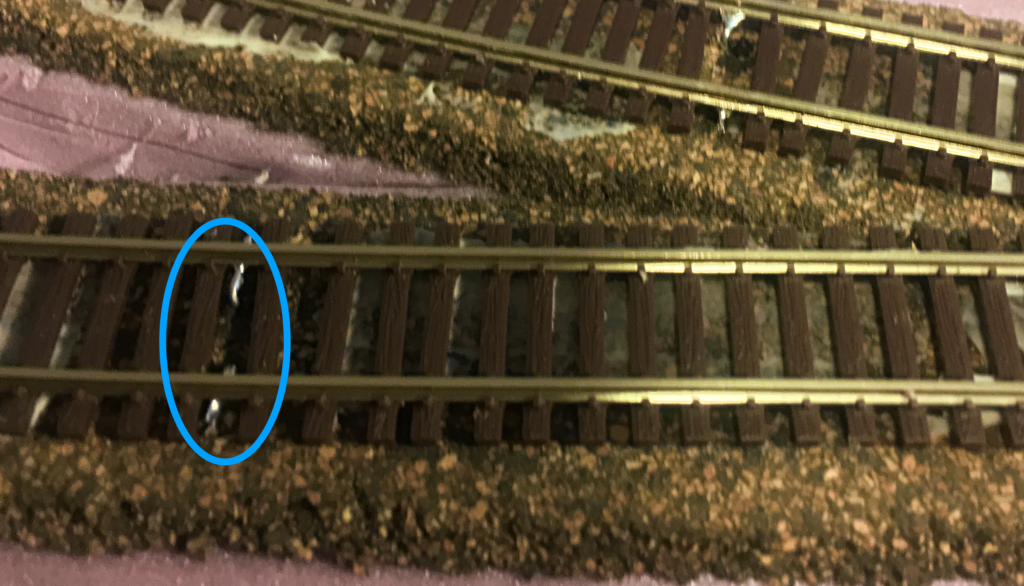
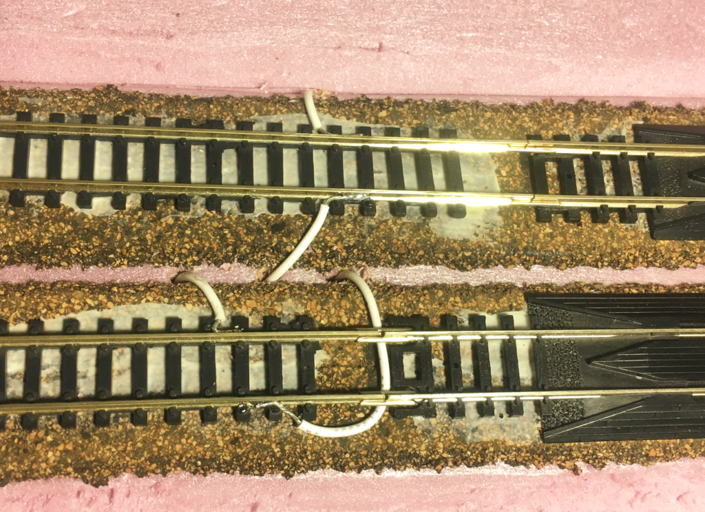
Needless to say, the above experimentation with various soldering wire to track techniques where a mixed success. I did a little research and I think I found a technique that I like. I came across a post about soldering on the CSX Dixie Line blog. They explained how they soldered wires to the bottom of the code 55 rail by moving the ties out of the way and soldering the wires crosswise (as shown in the image above). This keeps the wire at the bottom of the rail where it is hidden. It also reduces the amount of space taken up bo the joining on the bottom of the rail, only leaving a little gap that is easily covered up. Once the track is painted and ballasted, the wire should be practically invisible.
Wiring Turnouts
The old Atlas turnouts were non-power routing. Both routes remain active not matter which way they are thrown. I made sure that they had good power from all ends, and they would be happy.
I’ll admit that with the Peco turnout, I should have been more proactive with powering it. I didn’t add any additional wires. or connections. All of the power comes through the feeders attached to the short piece of track in front of it. Not exactly the most reliable set up. However, this saved me from having to come up with a way to change polarity of the frog and attached rails every time the turnout is thrown.
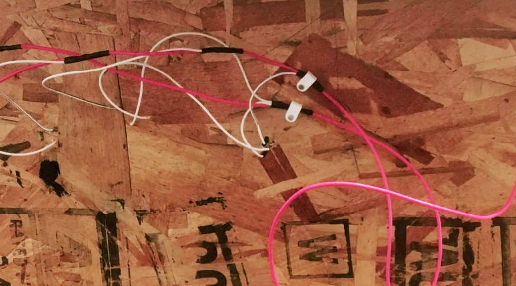
Under the layout 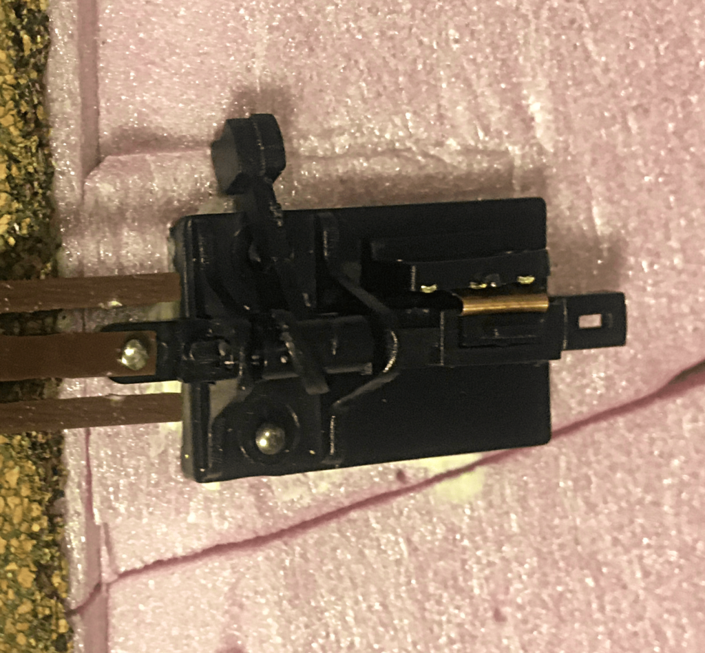
Top side
With fine scale Atlas turnout, the frog is isolated from the rest of the turnout. I need a way to power and reverse the frog’s polarity. To accomplish this, I used a Caboose Hobbies ground throw with a built in DTSP switch. The center lead of the switch was attached to frog. The other two leads were attached to their corresponding bus wires. Make sure that you keep your polarities straight or you’ll get a short when anything with metal wheels crosses the gap between frog a rail!
Underneath the Atlas switch, there are some soldering pads for attaching wires, one for each rail. There is also a soldering pad for the frog. If I where to do it again, I would use the technique stated above for tinning the pads and wires before attaching wires to the switch. If I had, I would have done a little less damage to the plastic tie that surrounded the pad.
Wires Under the Module
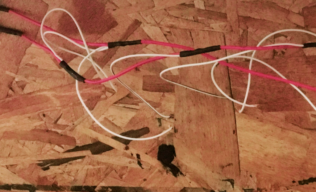
For the wiring underneath the module, I used two different sizes. The red wire is 18 gauge stranded. While this is a little light for a model railroad, this is about the perfect size for the module. No run is going to be too long that voltage drop would be an issue. For the feeder wires, I used white 24 gauge stranded wire. It just has to be long enough to reach from the bus wire to the track.
To help keep track of polarity, I marked one wire with a black stripe using a sharpie that I ran down the length of the wire. This made sure that I didn’t cross-wire any sections and get a short that would be hard to trace. It doesn’t matter which rail gets the wire with the black striped wire, as long as you are consistent.
Because of the size wire I am using, and the small number of connections that I need to make, I opted to solder the feeder wires to the bus wires instead of using suitcase connectors. If I were doing a larger layout, and I would be soldering underneath the layout, I would opt to use suitcase connectors.
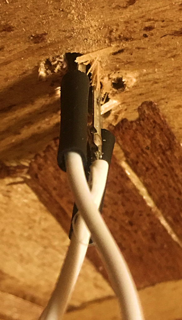
To make the connection, I used a stripper that pushed the insulation out of the way. I then slipped heat shrink tubing over the bus line just pass where I wanted to make the joint. I then soldered the feeder wire to the bus wire. Then I slipped the heat shrink tubing over the joint, and then used the heat of the soldering iron to shrink the tubing. Make sure that the joint is solid before doing adding heat to the heat shrink tubing, or you’ll have to cut off the tubing, unsolder the joint and try again.
Attaching Connections
After all of the feeder wires were attached, I then cut the two bus lines in half. I then installed a terminal strip and attached the bus wires to on side, making sure that I kept my polarities straight.
Front of Module 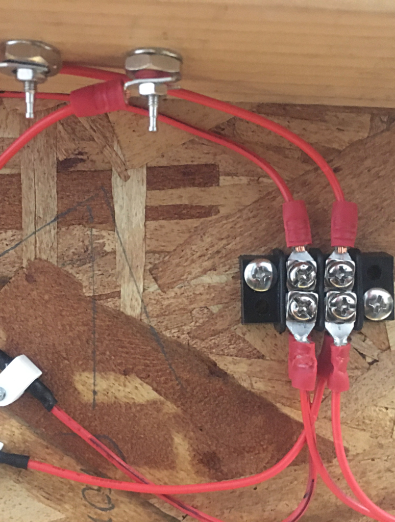
Underside of Module
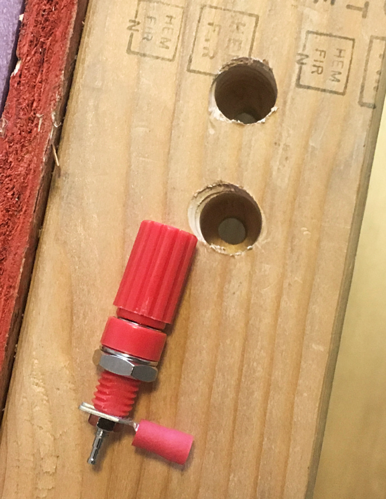
I then drilled two holes in the front 2×4 for two female banana plug terminals. installed them into the module. I then used crimp terminals to attache the wires to the back of the terminals. I then attached the wires to the other side of the terminal strip, again paying attention to my polarities.
Before 
After
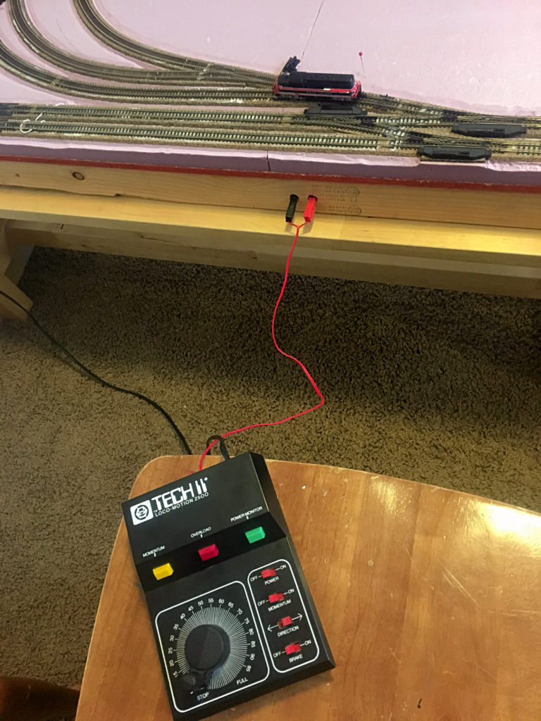
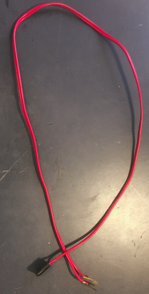
I had laying around a couple of old cables that came with some of those cheap model sets. Since I had multiple, I decided to use one for my module. I lopped off the black plug end. I then tested the wiring to make sure that the polarity is correct with the engine going in the direction selected on my DC power pack. I then connected the two male banana plugs to the cable. Now I have a way to easily attach a DC power pack to the module. When I decide to purchase a DCC system, the banana plugs make it easy to switch the module to it.
Wires Done!
Now the fun part, running an engine over the module and fixed any issues. At this point, I had a working track and could use to test with. Awesome!