
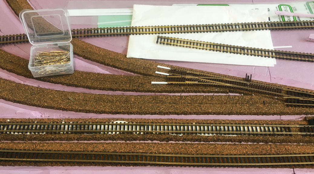
It is time to start laying track. Through my research and having laid the track on the module, I learned that this is one of the most important steps in building anything in model railroading. Take your time. Bad or uneven track will quickly ruin the fun in running trains.
One thing to note, I saved all ties that I removed from any track. I plan to use this to fill any gaps after the track is laid.
First Things First
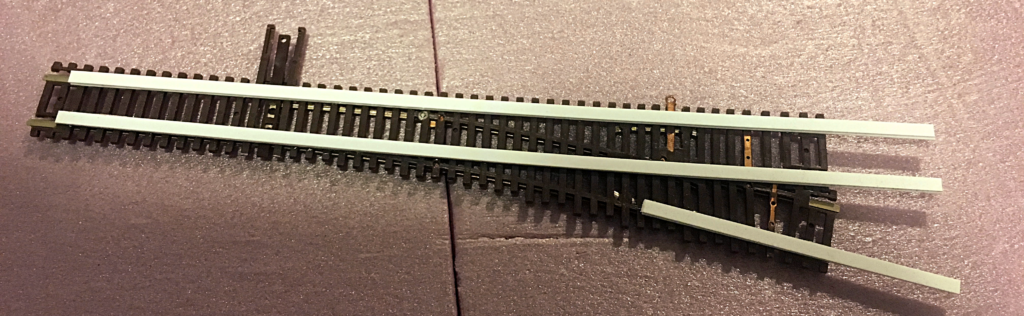
I found it easier to solder the leads onto the track before laying it. First plan where you want to put down your leads. Keep in mind where you have bracing or risers so you can avoid these obstacles. I prefer to solder the feeder wires to the bottom of the rails because I work with N scale, so this is a necessity.
If you have complicated track work, it might be easier to create subassemblies at your workbench, and then do final assembly on the layout. Test fit the pieces on the layout. Then take it to the workbench and then solder track pieces together. I used this technique with the crossover and siding turnout assembly. It was a lot easier to do this at the workbench.
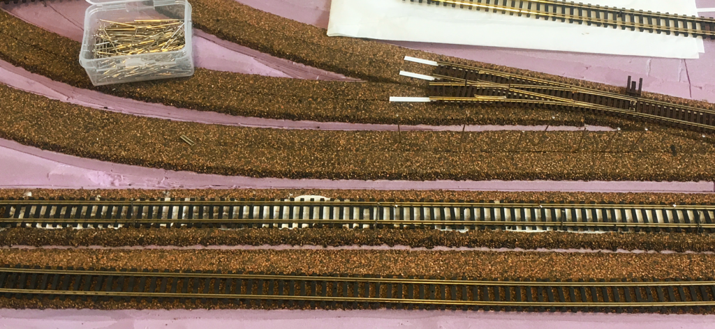
Putting Down Track
I originally thought about using track nails to hold down the track. However, there turned out to be one little problem with this idea. The sub-roadbed for the module is foam, and it won’t hold the spikes securely. I needed a plan ‘B’.
Fortunately, I have seen a number of times where they used caulk to hold the track to the cork. I figured I would give this technique a try. If you need help on how to do this, one place to go look is Model Railroader Video Plus (not sponsored). They have a number of videos show how to do this.
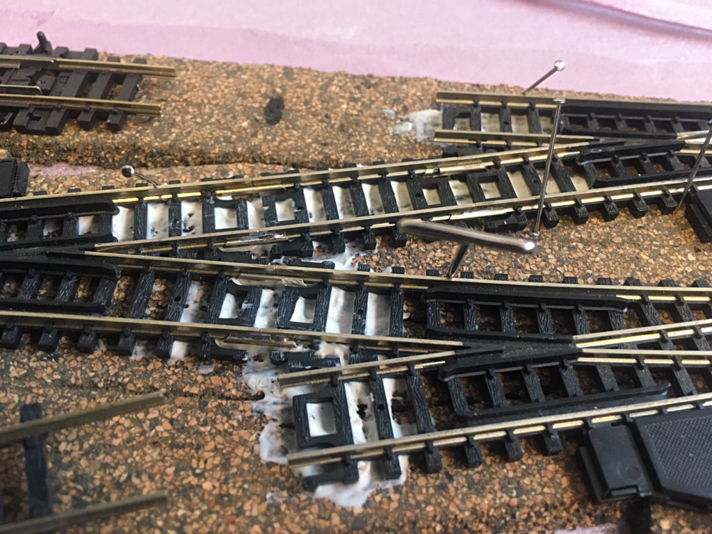
I first started with the most complex section of track, which is the crossover and spur turnouts. Using a caulk gun, I put down a bead of calk down the center of the cork in the section, making sure that I stayed away from the turnout points would be. I didn’t want to get any caulk into the works to gum things up.
After putting down the bead of caulk, run a small putty-knife down the direction of the bead. The goal is to flatten and spread out the caulk across the cork to give the track a nice sticky surface to sit in.
Now place the track on the cork, and make any adjustments you need, using pins as needed to keep things where you want it. Once the track is where you want it, then press it into the caulk. If you have a wallpaper roller, roll it along the top of the rails from the attached end to the free end. This helps set the track better than just pushing it into the caulk.
I then used pins and weight to help hold the track in place. Keep the pens and weight on that section until the caulk has cured enough that the track wont’ move, usually over 24 hours.
About the Turnouts
The turnouts used on the crossover on the main line are old Altas switches that I purchased years ago. They are ugly beastly things that I am not going to use anywhere else. I figured with the massive unpowered frog, if an engine ran over these without stalling, it was going to run just fine anywhere else on my future layout since I plan on using powered frog turnouts. To help with laying the crossover easier, I soldered all three old Atlas switches, plus track to help it all fit together, into one unit at the workbench.
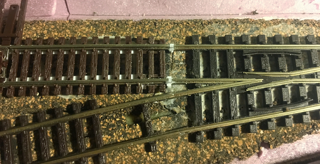
With the Peco switch, it is important to make sure that you electrically isolate both legs of the turnout from the connecting track to avoid shorts. I remembered to do this with the leg that connected to the Atlas Code 55 turnout, but neglected to do the same with the leg that connects to the curved piece of flex track. I didn’t discover this until I tested out the module with one of my engines, and it shorted out when I tried to go to the diverging route.
To isolate the Peco turnout, I glued a small piece of styrene in the rail joints between the turnout and the next section of track. I then filed the styrene to shape. Once the track is painted, the piece of styrene will be almost invisible.
The Atlas turnout had a couple of different issues in that it was at a different rail height than the Peco turnout, and it was warped. To fix this, I laminated a strips of .010 x .100″ and .020 x .100″ styrene together, since I didn’t have .030″ available to me at the time, to bring it up to the same rail height as the Peco turnout. I then glued it to the bottom of the turnout. In retrospect, I should have used wider strips to help give the caulk something more to grip onto. I left the strips long, and staggered the lengths so I could slope the connecting track back down to the cork. So far this has solution has worked out OK.
Replacing Ties
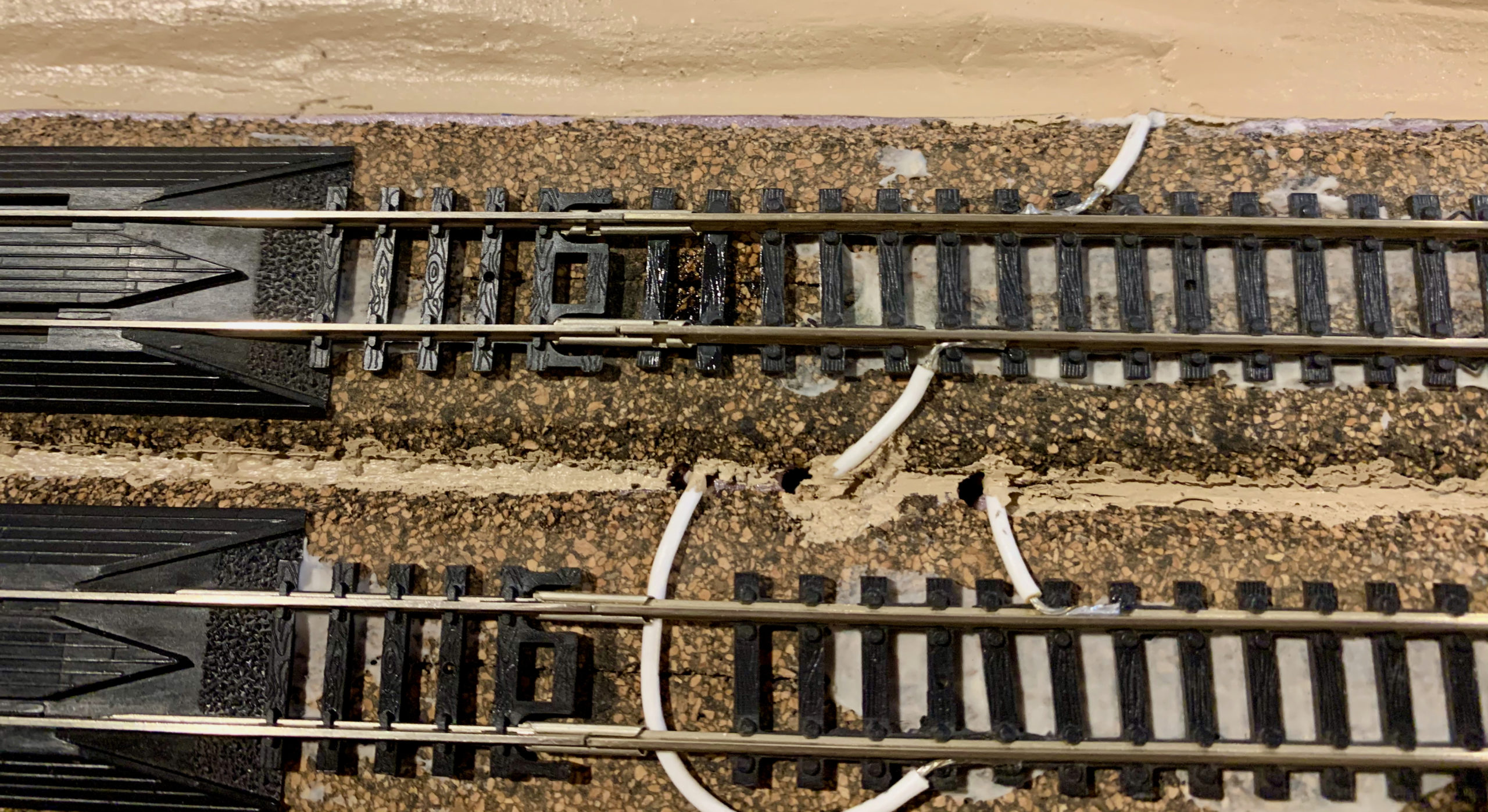
After the track was laid, there were a number of locations where the rail didn’t have ties because of wire feeders, rail joiners, etc. These bald spots will stand out even more when the track is painted and blasted. I took the ties that were removed in the rail laying process, and then glued them in place under the rails by applying CA to the bottom of the rail, and then sliding it in place.
There were a couple of places where the ties were too tall because of the leads. I sanded them down to size by rubbing the bottom fo the ties on a piece of medium to fine grit sandpaper until they were the correct size.