
In my last post, I went through how I built the base for my test module. Today I will continue the journey, and I will show you how I laid out the track diagram onto the foam.
To start off, I made a list of things that I wanted on the module:
- Different rail heights, starting with code 80 and working down to code 55.
- Set of sequential curves starting at 12″, and going up to 16″.
- Various turnout configurations to test movement through turnouts.
- Re-railers at the ends of the straight track to help with putting the equipment on the rails.
- Have enough room left over for some scenery.
To get an idea of how things would fit, I first started sketching out the track plan on paper. I wasn’t to concerned about making it exactly to scale, as I had the foam that I could adjust the layout on. I just wanted to see how I could arrange things, and how they would look.
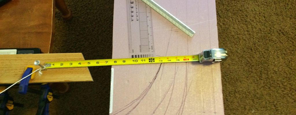
After a couple of sketches, I it was time to start transferring the track plan to the foam. I started first with the closest parallel track to the front edge since this was the most inflexible part of the track plan. Using a metal straight edge and a pencil, I drew the line on the foam. I then mocked up the crossover that would link the two parallel tracks together, and set it on the foam. This gave me a measurement of how far to place the second parallel track, which is about 1 1/4″ from the center line of the first track. I then marked where the second track will go.
With the parallel tracks marked, I then placed the other vital elements on the foam, including the other turnouts and the four re-railers, and marked their positions. With the turnouts, I marked where the frogs and points are located. I also marked where the ‘end’ of the turnout was. This will give me a better idea on where the turnouts end when I place the fexitrack later on. I laid out the rest of the straight track using a the metal straight edge.

I wanted to use easements on the curves. To help calculate the easements, I referenced Track Planning for Realistic Operation, Third Edition, by John Armstrong. On page 116, figure 9-8, John explains on how to layout easements, along with a nice graph that gives examples of how big of an easement to give to various radii in various scales. I used an offset of a 1/4″ for my curves from the inside of the tangent.
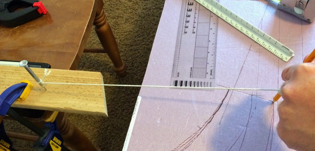
The curves coming off the two turnouts at the top half of the module where a little more tricky. I needed curves at 12, 14, and 16 inches. This issue at the time was that I couldn’t figure out a way to layout the curves as the center of the circles where off the edge of the module. The solution that I cam up with was to make a giant compass from a jeweler’s screwdriver, string, and a pencil. I drilled a couple of holes into a piece of scrap wood to hold the tip of the screwdriver. I then put the tip of the screwdriver into a hole. I then looped the string around the handle, and tied it off to form a ‘pivot’ point. This will keep the string from wrapping around the screwdriver as I made my arc, and thus preventing drawing a spiral. I tied on the other end of the string to the pencil. After clamping the whole thing to a chair, I had a crude compass that I could use to draw out my curves.
To use the compass, I used a tape measure to measure out the desired radius from the marked offset, to the middle of the screwdriver, moving the chair as necessary. I then wrapped the string around the pencil so the string was tight, and the point of the pencil so is tangent to my offset for the easements. I then used the pencil point to both scribe and draw an arc into the foam. Make sure that you keep the string tight and don’t rotate your pencil, or your curve will be off.
It is now time to finish off laying out the easements. In the diagram mentioned above, John Amrstrong explains that using long wooden stick, like a yard stick, to help draw the easements. Because I am dealing with N scale, and thus using a wooden stick would be way overkill, I used a metal hanger that came from the top of a hanging file used in file cabinets. It is flexible and straight enough for my needs. I pinned down one end of the hanger so it followed the straight tangent, and then pinned the other end so it followed the curve. The middle part was left to bend naturally from the straight section into the curve. I then used my pencil to mark along the hanger to complete the easement.
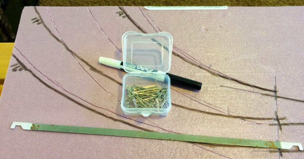
After all the lines have been drawn in the foam for the track, I used a black marker to highlight all of the lines. This made the lines a lot more visible. Especially since it took me many attempts to get the curves right.
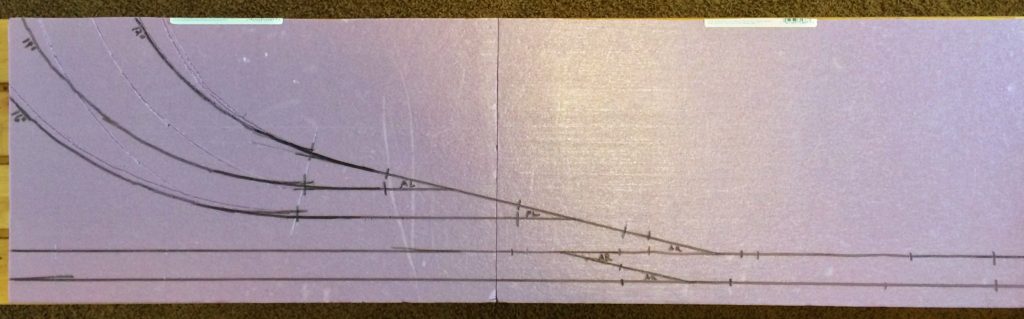
I now had my track diagram laid out on the foam. The next step is to start laying cork. I will let you how I did that in the next post.